Porównaj systemy
Systemy CDIF/3 + cechuje duża różnorodność funkcji diagnostycznych. Wersja Expert jest dodatkowo wyposażona w 10-cio kanałowy oscyloskop, generator sygnałów i napięć oraz sterownik elementów wykonawczych. Spójrz na tabelę poniżej przedstawiającą główne różnice.
Porównanie funkcji
 Nex |
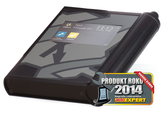 CDIF/3 + |
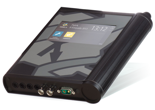 CDIF/3 Expert + |
|
|---|---|---|---|
| Odczyt i kasowanie kodów usterek | |||
| Odczyt bieżących parametrów | |||
| Aktywacje | |||
| Adaptacje | |||
| Kodowania | |||
| Rejestrator parametrów | |||
| Informacje techniczne | |||
| Menedżer serwisowy | |||
| WiFi | (2,4GHz i 5 GHz) | (2,4GHz i 5 GHz) | (2,4GHz i 5 GHz) |
| Bluetooth | |||
| Oscyloskop | |||
| Generator | |||
| Sterownik | |||
| Pass Thru |
Dane techniczne
Poniżej zostały przedstawione najważniejsze dane techniczne systemu CDIF/3 +, z szczególnym uwzględnieniem parametrów sprzętu. Dane te dotyczą wersji systemu obecnie dostępnych w sprzedaży a w związku z ciągłym rozwojem i ulepszaniem systemu CDIF/3 + zastrzegamy sobie prawo do zmiany tychże danych bez wcześniejszego uprzedzenia.
| Warunki środowiskowe | |
|---|---|
| Temperatura pracy | -20°C ~ +60°C |
| Wilgotność względna | 5% ~ 95% (bez kondensacji) |
| Stopień ochrony | IP30 |
| Obudowa | Aluminiowa |
| Zasilanie | |
| Źródło zasilania | Złącze diagnostyczne |
| Złącze USB | |
| Napięcie zasilania | 5 ~ 35V DC |
| Pobór prądu | typ. 0,3 A przy 13,8 V, maks. 2A |
| Diagnostyka | |
| Podstawowe standardy i protokoły | ISO9141, ISO9141-2, ISO14230, ISO15765, ISO11898, J2411, GMW3089, J1850 VPW, J1850 PWM, J1708, J2740, J2809, J2818, J2819, J2534 |
| Obsługa nietypowych protokołów | Tak |
| Praca w instalacjach 24 V | Tak |
| Złącze akcesoriów | 26-pin, kompatybilne z multiplekserem CDIF/2 |
| Multipleksowanie | Pełne (każdy sygnał na każdy pin) |
| Wyświetlacz | |
| Typ | Wyświetlacz kolorowy TFT z panelem dotykowym |
| Ekran | Matowy z pokryciem antyrefleksyjnym |
| Paleta kolorów | 262 tys. |
| Przekątna | 4,3’’ (95 mm x 54 mm) |
| Rozdzielczość | 480 x 272 |
| Podświetlenie | LED |
| Panel dotykowy | Rezystancyjny |
| Łączność | |
| Połączenie przewodowe | Złącze USB typu “B” |
| Połączenie bezprzewodowe | 802.11 b/g/n (WiFi 5GHz, 2.4GHz), Bluetooth |
| Zasięg | ok. 300m w terenie otwartym |
| ok. 50m w pomieszczeniach | |
| Tryb pracy bezprzewodowej | Klient lub access-point |
| Antena | Zewnętrzna, zamontowana na stałe |
| Oprogramowanie | |
| Obsługiwane systemy operacyjne | Android (od wersji 8.0), Windows 10 (32/64 bitowe) |
| Dodatkowe funkcje | |
| Rejestracja danych do pamięci wewnętrznej lub na kartę microSD | |
| Podstawowe funkcje diagnostyczne dostępne bez konieczności podłączenia komputera | |
| Akcesoria dodatkowe | |
| Zestaw do przenoszenia | |
| Kable diagnostyczne |
| Warunki środowiskowe | |
|---|---|
| Temperatura pracy | -20°C ~ +60°C |
| Wilgotność względna | 5% ~ 95% (bez kondensacji) |
| Stopień ochrony | IP30 |
| Obudowa | Aluminiowa |
| Zasilanie | |
| Źródło zasilania | Złącze diagnostyczne |
| Złącze USB | |
| Napięcie zasilania | 5 ~ 35V DC |
| Pobór prądu | typ. 0,3 A przy 13,8 V, maks. 2A |
| Diagnostyka | |
| Podstawowe standardy i protokoły | ISO9141, ISO9141-2, ISO14230, ISO15765, ISO11898, J2411, GMW3089, J1850 VPW, J1850 PWM, J1708, J2740, J2809, J2818, J2819, J2534 |
| Obsługa nietypowych protokołów | Tak |
| Praca w instalacjach 24 V | Tak |
| Złącze akcesoriów | 26-pin, kompatybilne z multiplekserem CDIF/2 |
| Multipleksowanie | Pełne (każdy sygnał na każdy pin) |
| Wyświetlacz | |
| Typ | Wyświetlacz kolorowy TFT z panelem dotykowym |
| Ekran | Matowy z pokryciem antyrefleksyjnym |
| Paleta kolorów | 262 tys. |
| Przekątna | 4,3’’ (95 mm x 54 mm) |
| Rozdzielczość | 480 x 272 |
| Podświetlenie | LED |
| Panel dotykowy | Rezystancyjny |
| Łączność | |
| Połączenie przewodowe | Złącze USB typu “B” |
| Połączenie bezprzewodowe | 802.11 b/g/n (WiFi 5GHz, 2.4GHz), Bluetooth |
| Zasięg | ok. 300m w terenie otwartym |
| ok. 50m w pomieszczeniach | |
| Tryb pracy bezprzewodowej | Klient lub access-point |
| Antena | Zewnętrzna, zamontowana na stałe |
| Oprogramowanie | |
| Obsługiwane systemy operacyjne | Android (od wersji 8.0), Windows 10 (32/64 bitowe) |
| Dodatkowe funkcje | |
| Rejestracja danych do pamięci wewnętrznej lub na kartę microSD | |
| Podstawowe funkcje diagnostyczne dostępne bez konieczności podłączenia komputera | |
| Akcesoria dodatkowe | |
| Zestaw do przenoszenia | |
| Kable diagnostyczne | |
| Sterownik | |
| Trzy niezależne wyjścia o definiowalnym poziomie sterowania ("+"/"-") | |
| Obciążalność | do 30A/kanał1 |
| Gniazdo przyłączeniowe | 4mm (tzw. bananowe) |
| Podstawowe tryby sterowania | "włącz/wyłącz", "pojedynczy impuls", "sekwencja impulsów", "sterowanie PWM" |
| Funkcjonalność | |
| Zaawansowane tryby sterowania ułatwiające sterowanie silnikami krokowymi, silnikami trójfazowymi, wtryskiwaczami benzynowymi, zaworami, silnikami prądu stałego itd. | |
| Możliwość modulacji czasu trwania impulsu lub wypełnienia PWM sygnałem z wejścia oscyloskopowego lub parametrem diagnozy szeregowej z użyciem dowolnie definiowalnych funkcji skalujących | |
| Synchroniczna lub asynchroniczna praca kanałów | |
| Zabezpieczenie przed przepięciami, zwarciem, przegrzaniem i przeciążeniem wyjść | |
| Definiowalne zabezpieczenie przeciążeniowe dla każdego wyjścia osobno | |
| Oscyloskop | |
| Cechy wspólne dla każdego kanału | |
| Próbkowanie | 2,4MSPS/kanał |
| Bufor | do 32k |
| Podstawa czasu | 10μs/div do 10s/div |
| Zakres pomiarowy | 5mV/div do 2kV/div2 |
| Dwa standardowe wejścia BNC | |
| Sprzężenie | stałoprądowe (DC) lub zmiennoprądowe (AC) |
| Pasmo | 1MHz |
| Impedancja | 1MΩ/50pF |
| Napięcie maksymalne | ±200Vpp |
| Dodatkowe trzy kanały dla obserwacji napięcia na wyjściach sterownika | |
| Dodatkowe trzy kanały dla obserwacji prądu na wyjściach sterownika | |
| Dodatkowe dwa kanały dla obserwacji sygnałów na wyjściach generatora | |
| Dodatkowy jeden kanał dla obserwacji napięcia akumulatora | |
| Funkcjonalność | |
| Zaawansowane tryby pracy, wyświetlania i wyzwalania | |
| Wyzwalanie z sygnału mierzonego lub z parametru/zdarzenia diagnozy szeregowej | |
| Możliwość jednoczesnej obserwacji sygnałów na wszystkich lub wybranych kanałach | |
| Możliwość wyświetlania sygnału w dowolnych jednostkach fizycznych, z użyciem dowolnie definiowalnych funkcji skalujących | |
| Generator | |
| Jeden kanał małosygnałowy, precyzyjny (do emulowania czujników) | |
| Napięcie wyjściowe | -2,5V do +2,5V |
| Obciążalność prądowa | do 50mA |
| Sprzężenie | stałoprądowe (DC) lub zmiennoprądowe (AC) |
| Próbkowanie | 1MSPS |
| Bufor | do 32k |
| Gniazdo przyłączeniowe | BNC3 |
| Jeden kanał dużej mocy (do zasilania lub sterowania) | |
| Napięcie wyjściowe | 0V do +25V |
| Obciążalność prądowa | programowalna, od 0A do 5A |
| Próbkowanie | 1MSPS |
| Bufor | do 32k |
| Gniazdo przyłączeniowe | 4mm (tzw. bananowe) |
| Funkcjonalność | |
| Bezpośrednia cyfrowa synteza sygnałów (DDS) | |
| Oba kanały mogą pracować asynchronicznie (osobne ustawienia każdego kanału) lub synchronicznie (wspólne ustawienia obu kanałów) | |
| Możliwość generowania sygnałów o dowolnym kształcie (generator arbitralny) | |
| Wbudowana biblioteka sygnałów wzorcowych, rozszerzalna o własne sygnały, w tym zarejestrowane za pomocą oscyloskopu | |
| Możliwość generowania sygnałów uprzednio zarejestrowanych za pomocą oscyloskopu | |
| Praca samobieżna, wyzwalana lub synchronizowana sygnałem z wejść BNC oscyloskopu lub parametrem/zdarzeniem diagnozy szeregowej | |
1 -
Sumaryczny prąd wszystkich kanałów nie może przekroczyć 60A.
2 - Zakres powyżej 20V/div dostępny dla sond z dzielnikiem oraz sond wysokiego napięcia.
3 - Wyjście współdzielone z wejściem drugiego kanału oscyloskopu.
2 - Zakres powyżej 20V/div dostępny dla sond z dzielnikiem oraz sond wysokiego napięcia.
3 - Wyjście współdzielone z wejściem drugiego kanału oscyloskopu.
| Warunki środowiskowe | |
|---|---|
| Temperatura pracy | -20°C ~ +60°C |
| Wilgotność względna | 5% ~ 95% (bez kondensacji) |
| Stopień ochrony | IP30 |
| Obudowa | Tworzywo sztuczne |
| Zasilanie | |
| Źródło zasilania | Złącze diagnostyczne |
| Złącze USB | |
| Napięcie zasilania | 5 ~ 35V DC |
| Pobór prądu | typ. 0,3 A przy 13,8 V, maks. 2A |
| Diagnostyka | |
| Podstawowe standardy i protokoły | ISO9141, ISO9141-2, ISO14230, ISO15765, ISO11898, J2411, GMW3089, J1850 VPW, J1850 PWM, J1708, J2740, J2809, J2818, J2819, J2534 |
| Obsługa nietypowych protokołów | Tak |
| Praca w instalacjach 24 V | Tak |
| Złącze akcesoriów | 26-pin, kompatybilne z multiplekserem CDIF/2 |
| Multipleksowanie | Pełne (każdy sygnał na każdy pin) |
| Łączność | |
| Połączenie przewodowe | Złącze USB typu “B” |
| Połączenie bezprzewodowe | 802.11 b/g/n (WiFi 5GHz, 2.4GHz), Bluetooth |
| Zasięg | ok. 300m w terenie otwartym |
| ok. 50m w pomieszczeniach | |
| Tryb pracy bezprzewodowej | Klient lub access-point |
| Antena | Wewnętrzna |
| Oprogramowanie | |
| Obsługiwane systemy operacyjne | Android (od wersji 8.0), Windows 10 (32/64 bitowe) |
| Akcesoria dodatkowe | |
| Zestaw do przenoszenia | |
| Kable diagnostyczne |