CDIF/3 +
Interfejs CDIF/3 + jest uniwersalnym urządzeniem, które bez konieczności stosowania dodatkowych akcesoriów obsługuje wszystkie spotykane w pojazdach standardy komunikacji i diagnozy.
Funkcje diagnostyczne
Identyfikacja
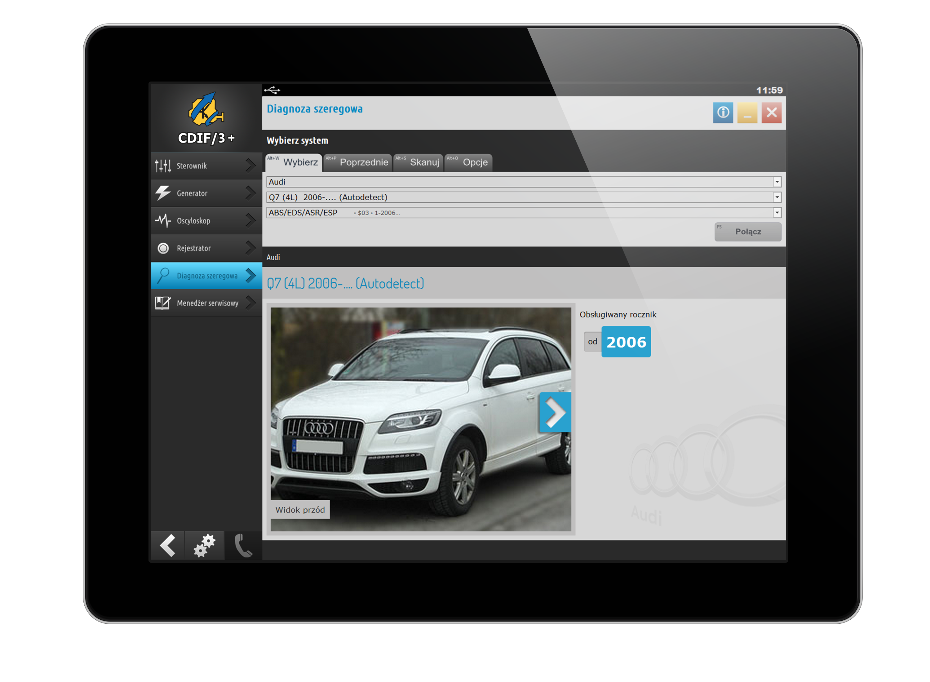
Identyfikacja jest funkcją diagnozy szeregowej, która pozwala na wgląd w szereg informacji o systemie, który diagnozujesz. To właśnie tu otrzymuje się szczegółowe dane sterownika - numery części, wersje wyposażenia, datę produkcji lub ostatniej wizyty w serwisie, kod silnika lub systemu.
Zastosowanie:
- zamów części zamienne na podstawie danych ze sterownika
- zweryfikuj poprawność wyboru komponentu
- oceń występowanie określonych elementów wyposażenia
Odczyt i kasowanie kodów usterek
Najczęściej wykorzystywaną funkcją diagnozy szeregowej jest odczyt i kasowanie kodów usterek. Dzięki tej funkcji możemy odczytać zarejestrowane podczas pracy systemu błędy, ułatwiając diagnozę i pozwalając skrócić czas naprawy. CDIF/3 oferuje w tym zakresie imponujące możliwości. Jednym kliknięciem możemy odczytać usterki, prezentowane czytelnie w postaci odpowiedniego kodu wraz z szczegółowym opisem.
Zastosowanie:
- mechanik otrzymuje informację o tym czy występują usterki w diagnozowanym samochodzie
- dowiedz się czy usterka występuje teraz czy została zapamiętana w przeszłości
- system niekiedy podpowiada symptomy, dzięki którym łatwiej zdiagnozujesz problem
Parametry bieżące
Wgląd w szczegóły pracy danego systemu jest istotny w procesie oceny prawidłowości jego działania. CDIF/3 umożliwia nam na bieżąco obserwację parametrów pracy, zarówno w postaci czytelnej tabeli najbardziej aktualnych i precyzyjnych danych jak i w postaci graficznego wykresu zmian tych parametrów w czasie.
Zastosowanie:
- obserwacja wszystkich możliwych parametrów jednocześnie
- można wybrać tylko interesujące nas parametry
- możliwość eksportu listy parametrów do różnych dokumentów, w tym MS Excel w celu późniejszego wglądu
Aktywacje
Nie wszystkie usterki dają się wykryć przez wbudowane w sterownik możliwości samotestowania. Jak zawsze, najlepszym diagnostą jest ucho i oko mechanika. Dlatego sterowniki instalowane w samochodach pozwalają na wykonanie określonych aktywacji, dzięki którym można ocenić prawidłowość wysterowania elementów wykonawczych.
Zastosowanie:
- testy układu zapłonowego, wtryskowego, sterowania zaworami
- testy układów elektronicznych
Adaptacje
Nierzadko występuje potrzeba regulacji systemu - ustawienia biegu jałowego, zmiana dawki paliwa, skalibrowania przepustnicy lub skasowania kontrolki oleju. Funkcje te są dostępne w CDIF/3 pod postacią łatwych do przeprowadzenia adaptacji. Funkcje adaptacji w systemie CDIF/3 zrealizowano tak, aby średnio zaawansowany mechanik mógł szybko i łatwo dokonać odpowiednich regulacji.
Zastosowanie:
- skasowanie kontrolki oleju
- ustawienie biegu jałowego
- dopalenie filtra DPF
- zmiana dawki paliwa
- skalibrowanie przepustnicy
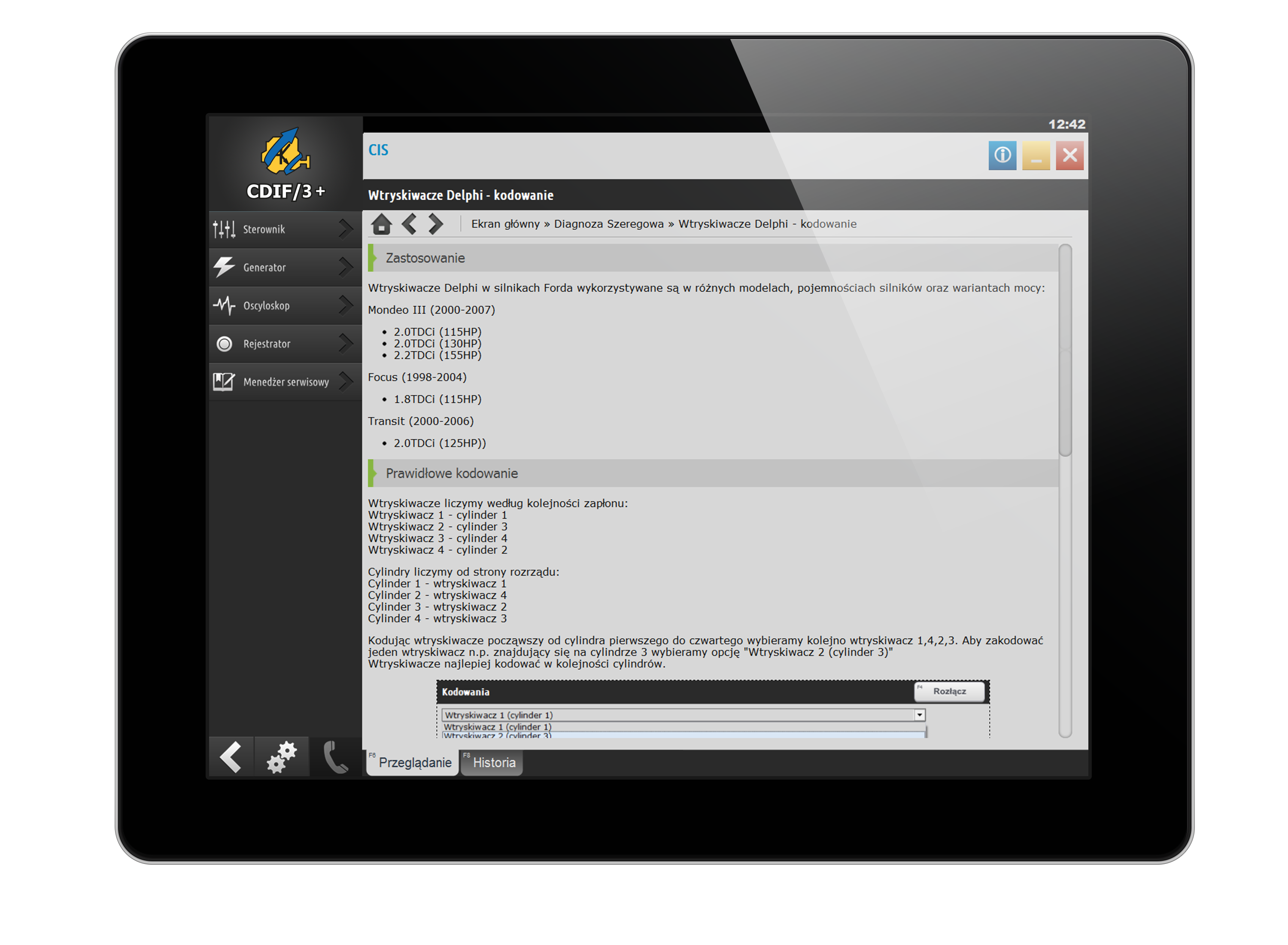
Kodowania
Kodowanie umożliwia zmianę ustawień sterownika - włączenie lub wyłączenie określonych funkcji, dostosowanie opcji do wyposażenia lub modelu pojazdu itd.
Zastosowanie:
- kodowanie wtryskiwaczy
- zmianę konfiguracji poduszek powietrznych
- dopasowanie typu przekładni
- wybór trybu pracy silnika


CDIF/3 + w liczbach
lat rozwoju, marek samochodów, modeli,
+ diagnozowalnych komponentów.
+ diagnozowalnych komponentów.
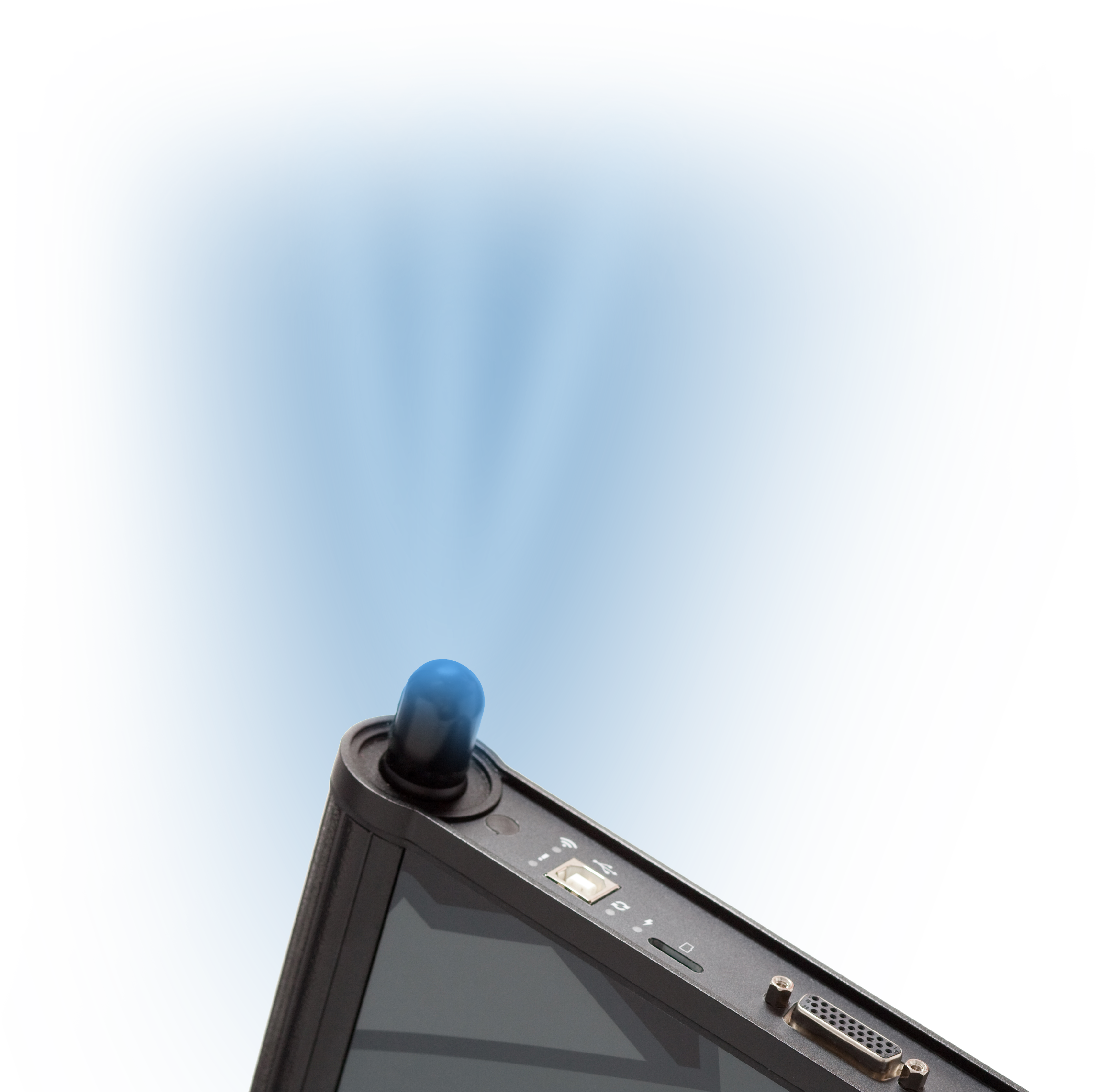
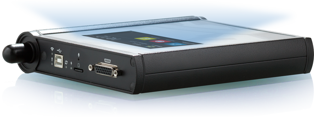
Budowa
0%
 Wbudowana antena WiFi i moduł Bluetooth
 Dotykowy wyświetlacz LCD TFT
 Karta SD
 Solidna konstrukcja
 Dożywotnia gwarancja
Wbudowana antena WiFi zapewnia doskonały zasięg w zamkniętych pomieszczeniach. Dzięki wykorzystaniu standardu "n" komunikacja jest szybka i pewna!
Dotykowy wyświetlacz udostępnia podstawowe funkcje diagnostyczne bez konieczności podłączenia komputera, a jego obsługa jest prosta i intuicyjna.
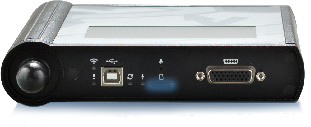
CDIF/3 + został wyposażony w kartę SD, co umożliwia rejestrację dużej ilości danych diagnostycznych oraz uruchamianie samodzielnych programów diagnostycznych.
Podłącz i pracuj ...
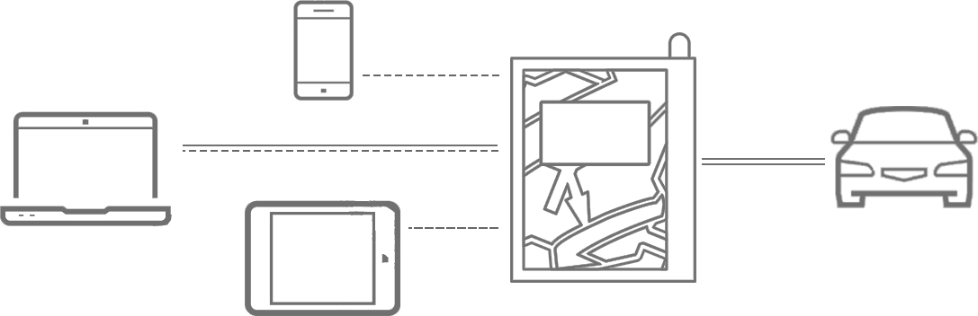
 Połączenie WiFi lub Bluetooth
 Połączenie WiFi lub Bluetooth lub USB (do wyboru)
 Połączenie poprzez adapter diagnostyczny
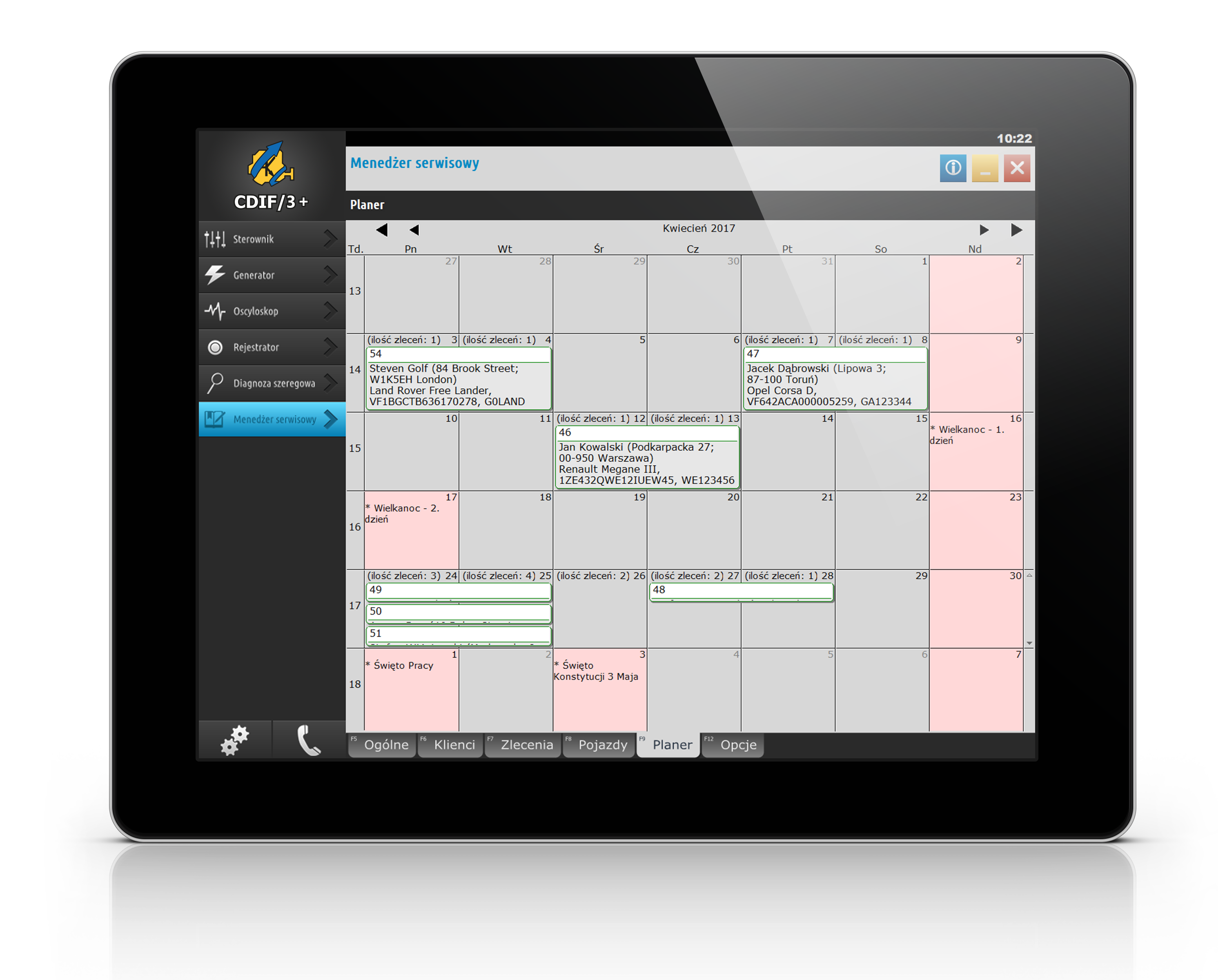
Menedżer serwisowy
Zorganizuj swój warsztat, zarządzaj pracą warsztatu.
Menedżer serwisowy jest idealnym prostym narzędziem biurowym potrzebnym w każdym warsztacie.
Menedżer serwisowy jest idealnym prostym narzędziem biurowym potrzebnym w każdym warsztacie.
Planer
Planuj zlecenia na przyszłość
Zorganizuj pracę warsztatu
Zorganizuj pracę warsztatu
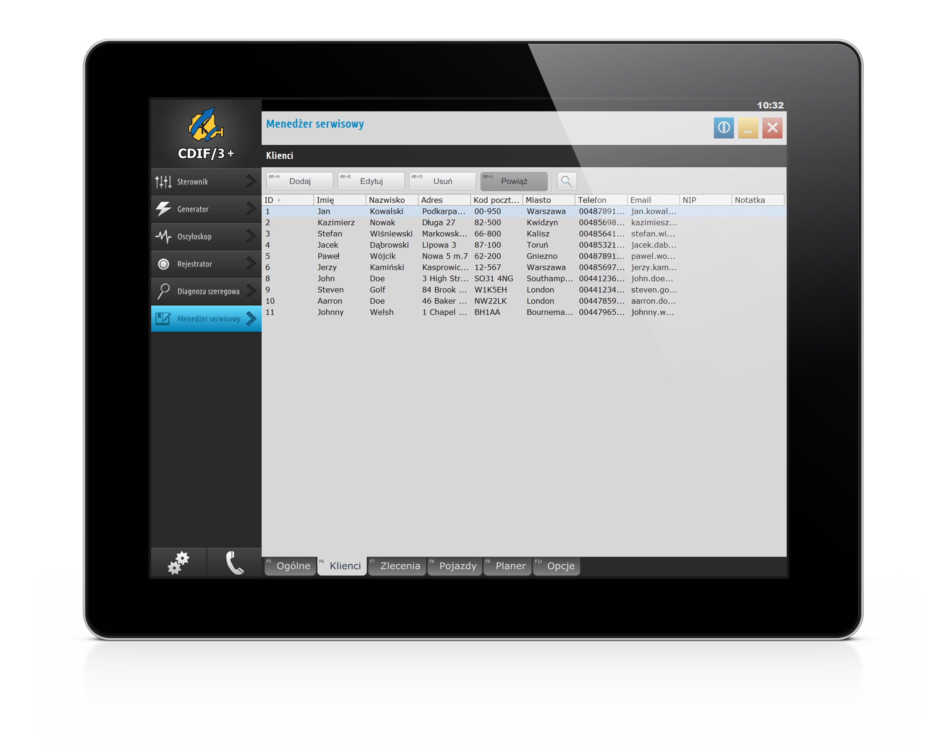
Baza klientów
Utwórz listę klientów
Wyszukaj klienta w bazie
Użyj jego danych do raportów i zleceń
Wyszukaj klienta w bazie
Użyj jego danych do raportów i zleceń
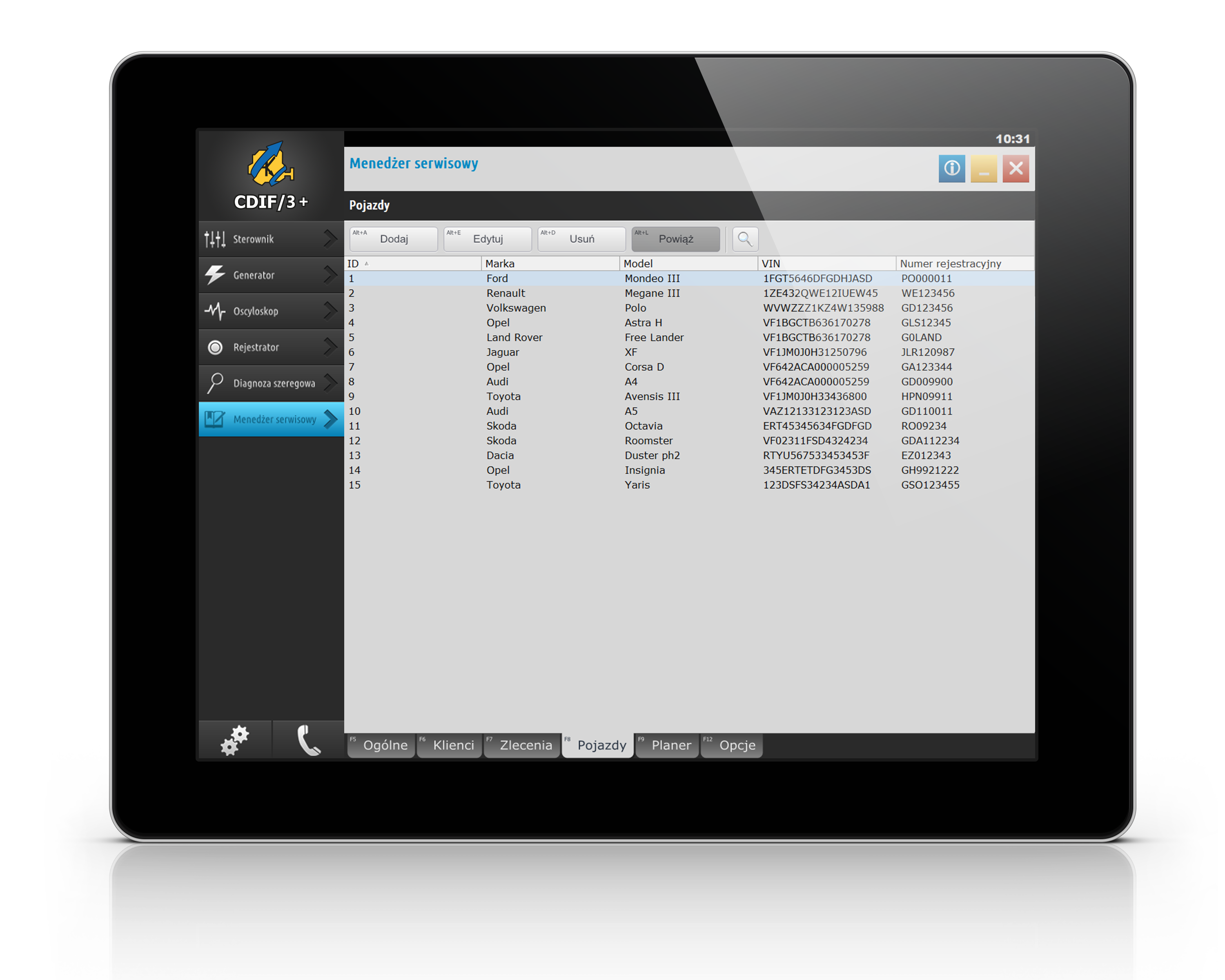
Baza pojazdów
Trzymaj szczegółowe dane samochodu
Na podstawie VIN szybciej zamówisz części
Stwórz własną historię serwisową samochodu
Na podstawie VIN szybciej zamówisz części
Stwórz własną historię serwisową samochodu
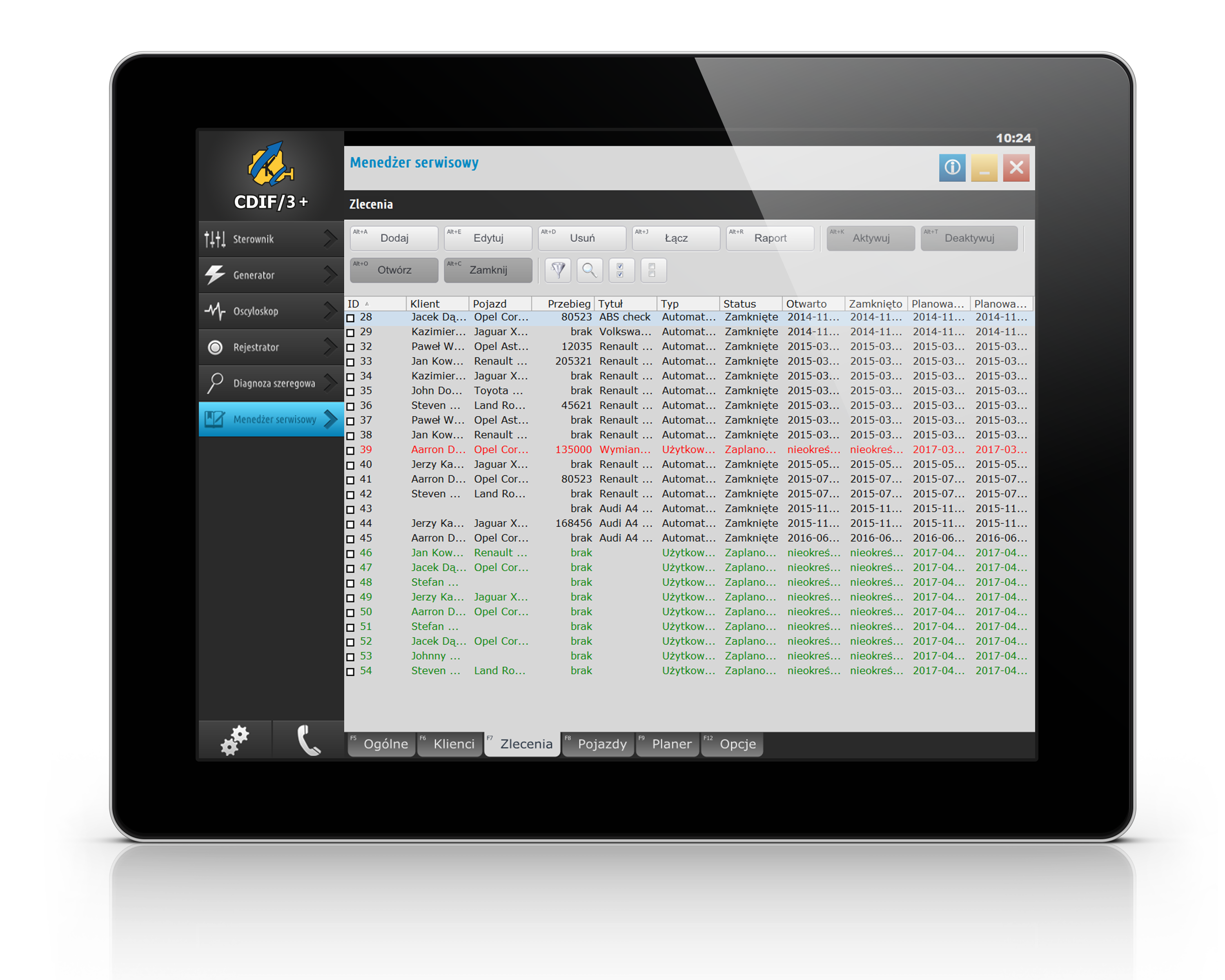
Zlecenia i raporty
Twórz zlecenia naprawy
Drukuj raporty dla klientów
Przeglądaj historię napraw
Drukuj raporty dla klientów
Przeglądaj historię napraw
Informacje techniczne
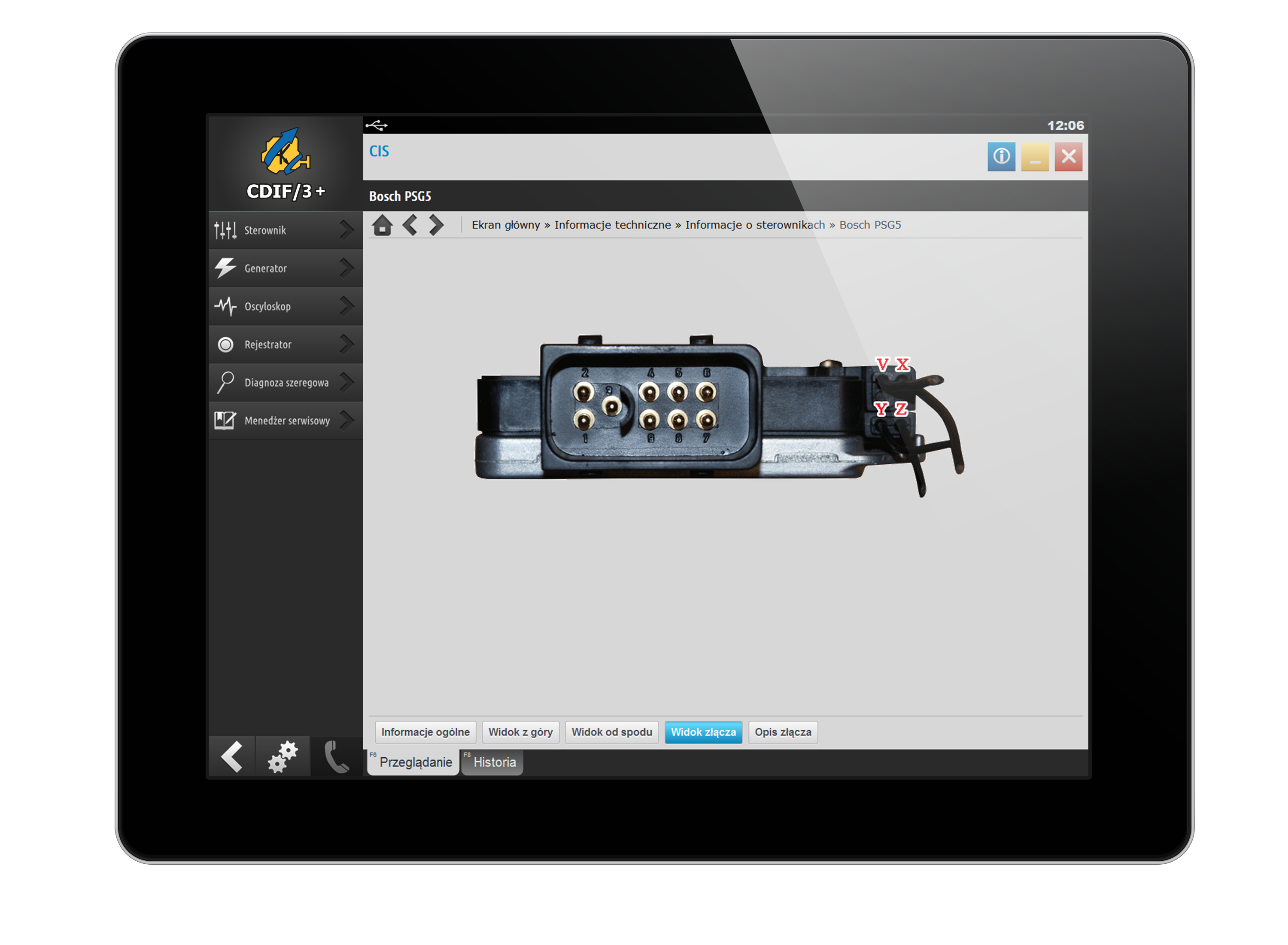
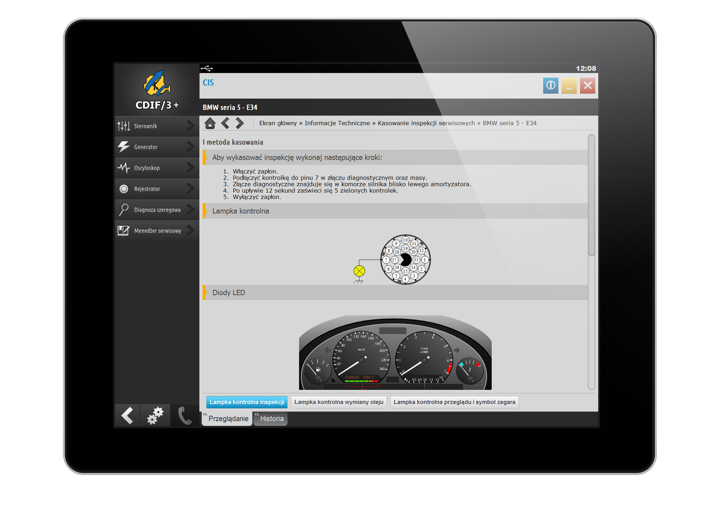
W ramach systemu informacji technicznych CIS realizowana jest stale poszerzana baza materiałów, które powiązane z prowadzonym procesem diagnozy, wspomagają mechanika przy likwidacji usterek.
Co znajduje się w bazie CIS:
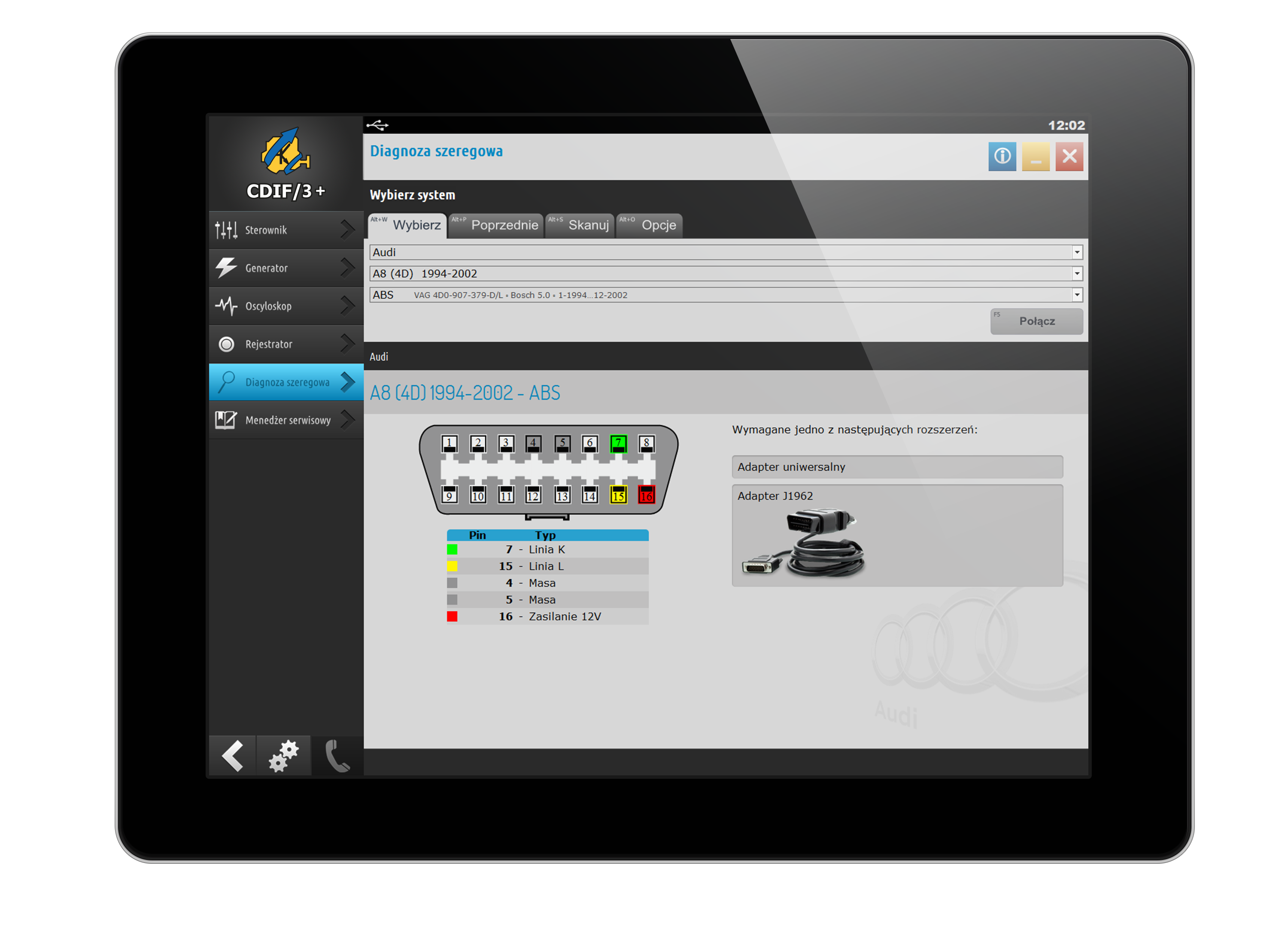
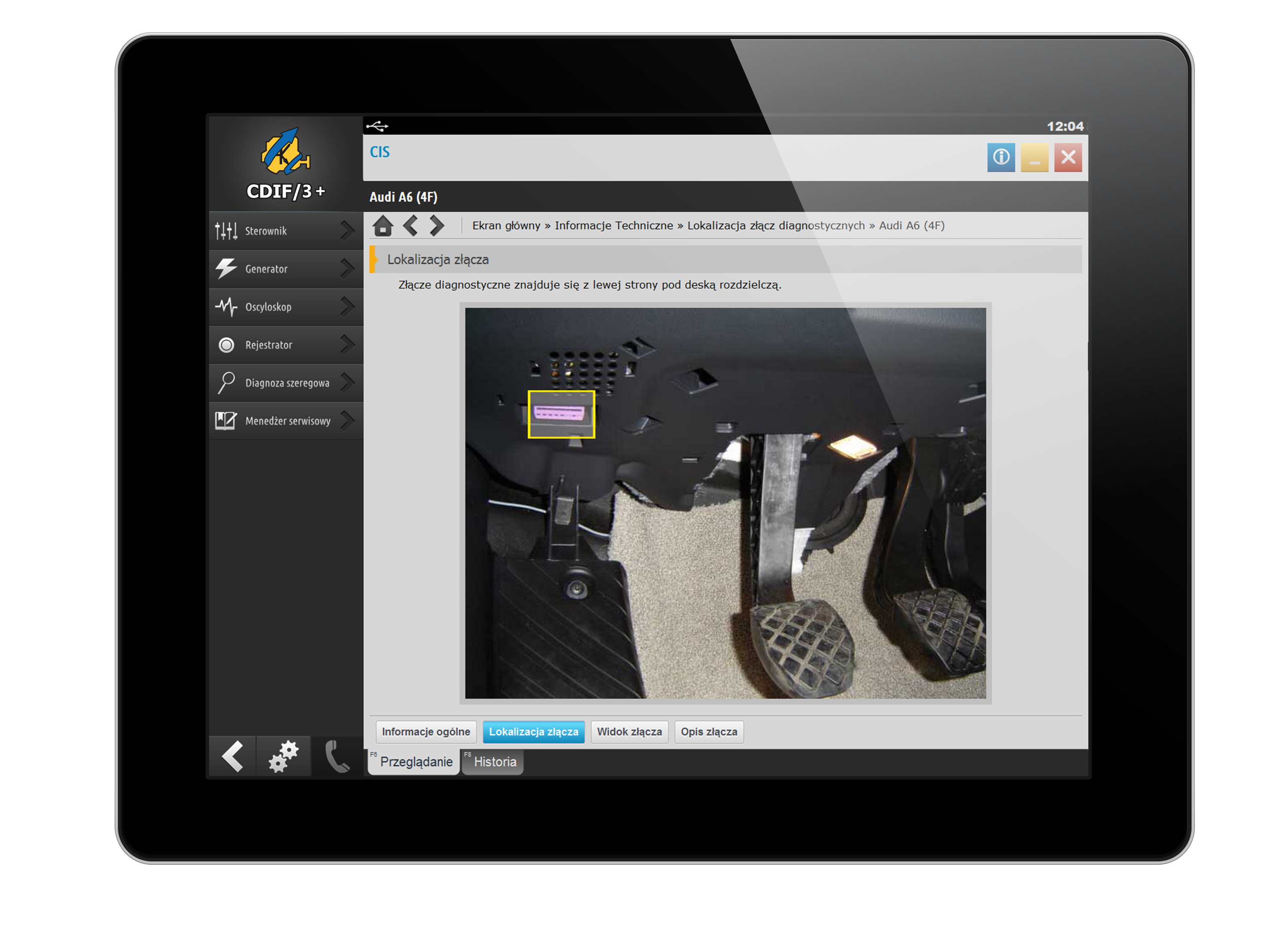
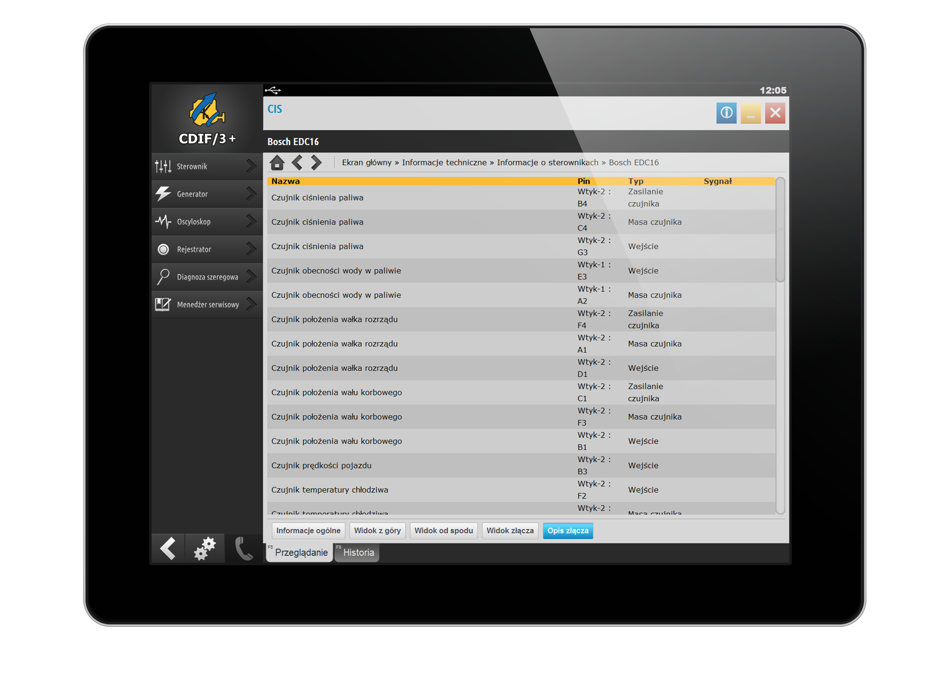
- Lokalizacja złączy diagnostycznych, ich wygląd i sygnały na nich występujące
- Zdjęcia diagnozowanych modeli samochodów
- Instrukcje kasowania inspekcji serwisowych
- Poradniki w diagnozie
Wsparcie
6 miesięcy wsparcia technicznego GRATIS
W ramach abonamentu otrzymasz wsparcie techniczne oraz dostęp do najnowszych aktualizacji, które pojawiają się w cyklu dwumiesięcznym.
Po upływie abonamentu możesz go przedłużyć na atrakcyjnych warunkach lub kontynuować pracę na obecnej wersji oprogramowania.
Szkolenia
Najlepszą metodą na start jest wzięcie udziału w szkoleniu, organizowanym przez Autoryzowane Centra Szkoleniowe CDIF/3 ! Tematyka szkolenia dopasowana jest do potrzeb początkujących.
Więcej o szkoleniach